Mechanical & CADEngineering Study
DFM Architecture & Injection Mold Optimization for IP67 IoT Enclosure
An outdoor IoT gateway required a robust IP67 enclosure capable of enduring UV exposure, vibration, and thermal cycling. YantriX delivered the full 3D CAD design, DFM analysis, moldflow optimization, and ASME Y14.5 production drawings, releasing to tooling with zero rework iterations.
By YantriX Engineering · CAD & DFM Studio2 min readIndustrial IoT & Smart Infrastructure
Overview
Engineering Scope & Context
Complete CAD design and DFM optimization for a multi-part outdoor IoT enclosure in polycarbonate — 1.5° uniform draft, overmolded silicone gasket, and moldflow sink-mark elimination.
Engagement: Engineering Study
Discipline: Mechanical & CAD
Project Type: Mechanical CAD Design + DFM + Moldflow Analysis
Application: Industrial IoT & Smart Infrastructure
Key specifications
Core engineering parameters & stack.
- IP67
- Water-tight sealing standard
- 1.5°
- Uniform draft angle design
- 2.8 mm
- Nominal wall thickness
- ASME
- Y14.5 GD&T drawings
Objectives
What the project needed to achieve
- Redesign internal and external geometry with uniform 2.8 mm wall thickness and ≥1.5° draft angles
- Engineer a compressed silicone O-ring gasket channel guaranteeing IP67 ingress protection
- Perform moldflow analysis to eliminate sink marks, knit lines on critical mounting bosses, and air traps
- Deliver complete ASME Y14.5 GD&T production drawings for toolmaker fabrication
Challenge
Engineering constraint
The client's initial CAD concept for a pole-mounted smart-grid gateway suffered from non-uniform wall thicknesses, zero draft on deep ribs, and an unfeasible gasket channel that leaked during initial SLA testing. With tooling costs estimated at ₹18 lakh for a 2-cavity hardened steel mold, they could not afford tooling rework or sink-mark defects on textured aesthetic faces.
Approach
How YantriX approached the work
- 01
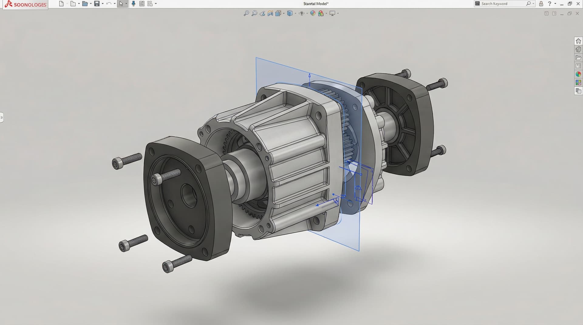
Rebuilt the parametric CAD model in SolidWorks with master-model surfacing, ensuring draft compliance across all 42 shut-off faces and internal PCB standoffs.
- 02
Optimized rib-to-wall ratios (0.55× nominal wall) and incorporated coring to prevent sink marks on textured exterior surfaces.
- 03
Simulated injection molding fill, pack, and warp in Autodesk Moldflow, relocating gates to push weld lines away from structural screw bosses.
- 04
Designed a captive tongue-and-groove silicone gasket groove with 30% compression ratio calculated for IP67 sealing under bolt pre-loads.
- 05
Generated 2D manufacturing drawings specifying tooling tolerances (ISO 2768-mK), SPI-A2 optical finish for status LEDs, and MT-11010 texture for housing.
Outcomes
What improved by the end
- First-shot tooling samples passed IP67 submerged water-ingress testing (1m for 30 min) without modification
- Zero sink marks or visible weld lines on cosmetic exterior surfaces
- Tooling cycle time optimized to 38 seconds per shot
- Toolmaker released mold to production in 6 weeks with zero tooling change orders (ECNs)
Deliverables
What the client receives
- Parametric SolidWorks master assembly (.sldasm / .sldprt) + neutral STEP files
- DFM & Moldflow simulation report with gate, runner, and cooling channel notes
- ASME Y14.5 2D production drawings with full GD&T and surface finish callouts
- BOM with silicone gasket specifications and fastener torque ratings
Tools used
Stack and tooling
- SolidWorks (Parametric Master Model)
- Autodesk Moldflow Adviser
- KeyShot for client CMF presentation
- ASME Y14.5-2018 GD&T Standards
Impact
Business-level effect
- Tooling approved on the first test run, saving 6 weeks of commercial launch delay
- Over ₹4.5 lakh saved in potential tool modification and EDM electrode rework costs
- Enclosure passed 1,000-hour UV chamber and thermal cycling tests (-20 °C to +70 °C)
Conclusion
Proper DFM isn't an afterthought checklist — it's an engineering discipline where draft, wall thickness, gating, and tooling parting lines guide the CAD from day one.
Working on a similar engineering problem?
Preparing plastic or metal CAD for tooling release? Send us your 3D model for a comprehensive DFM review before cutting steel.
Tagged
- CAD
- DFM
- Injection Molding
- SolidWorks
- IP67
- Enclosure Design
Visual results
Key views and intermediate artefacts
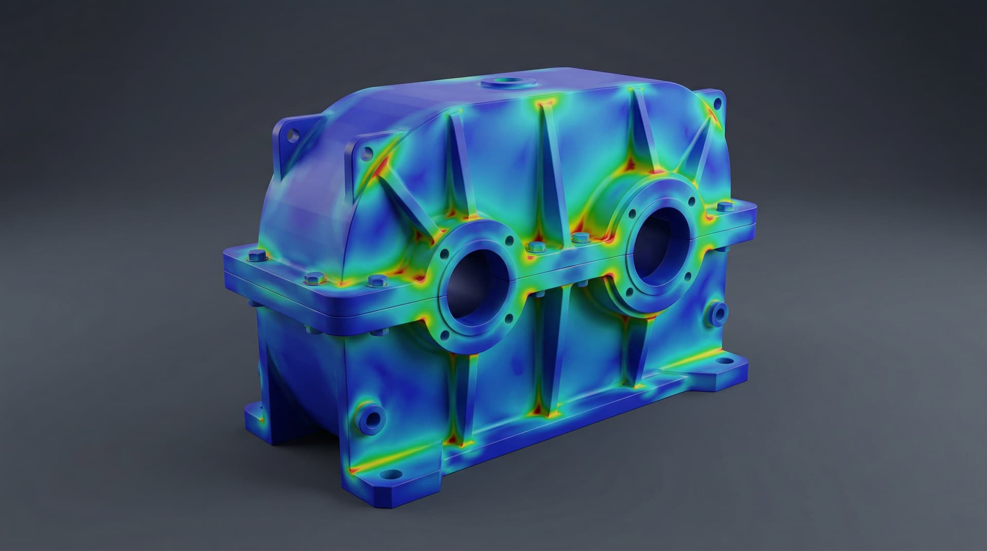
Moldflow fill & sink mark analysis
Frequently asked questions
Answers from the engagement itself.
How early in product design should DFM begin?
From the first parametric solid. Defining parting lines, draft angles, and uniform wall thickness early prevents 80% of downstream tooling delays.
What is the minimum draft angle required for injection molding?
We recommend a minimum of 1.0° for smooth polished cores and 1.5°–3.0° for textured cosmetic cavity faces to prevent drag marks during ejection.
Related case studies
Adjacent proof you can read next.
CAD Design · Sheet Metal & Enclosures
Sheet Metal Industrial Inverter Enclosure CAD & DFM Optimization
Parametric CAD design for an industrial solar inverter enclosure — K-factor bend deduction, PEM hardware spacing, thermal louvers, and flat-pattern DXF export.
ML-accelerated engineering
Surrogate Modeling for Accelerated FEA Design Exploration
A physics-informed neural network trained on 12,000 ANSYS runs replaces the full solver for early-stage topology — predicts stress fields in 40 ms vs. 22-minute solves.
Continue exploring
Related blogs, services, and capability pages
Cross-links help readers move from proof into capability and educational content, and they reinforce the crawl path between commercial pages and reference content.
Similar Engineering Need?
Need help developing something similar?
Discuss your dfm architecture & injection mold optimization for ip67 iot enclosure requirements, design challenges, or target specifications with our engineering team. NDA support is available where required.